A digital milliohmmeter (microohmmeter), microvoltmeter, and accurate ESR meter based on STM32F373 processor and AD8253 instrumentation amplifier
A relatively simple and cheap "open hardware" DIY hobby construction with schematics and open source GPLv3 firmware.
One of the tasks which even a high-end multimeter definitely cannot perform is the measurement of low resistances. It can be needed to check quality of connectors, switches and relays etc., to check various current sensing resistors, heating elements, measure DC resistance of inductors and check windings opens or shorts in motors, generators and transformers etc. Since specialized low-production-volume test equipment is expensive, here a room for a do-it-yourself construction is open.Moreover, since a failed aluminum electrolytic capacitor is the number one source of failures of the ubiquitous switch mode power supplies, it is handy for a repairman to have an ESR meter (essentially an AC milliohmmeter) to check the equivalent series resistance (ESR) of capacitors.
There are at least two possibilities how to measure ESR of capacitors, one of them a balanced bridge configuration, where the DUT capacitor's resistance will bring the bridge out of balance, while high enough measurement frequency is used to keep the reactive component negligible. The other method uses fixed current pulses short enough to charge the capacitor only negligibly and measures the voltage drop on the capacitor's ESR according to the Ohm's law.
I have adopted the bridge configuration in a previous ESR-meter construction which works well enough to find a defect capacitor, but is not really accurate for low-ESR capacitors and capacitors above 1000uF. The device described below uses the pulse-type approach, in addition to DC measurement of low resistances and ESR of inductors.
The basic principle of the device is very simple - just the Ohm's law - but as usually the devil is in the details. To achieve high accuracy, it is necessary to cancel noise and ADC offset in some way. A standard approach is to use the lock-in amplifier - test current is modulated and the signal is integrated with positive sign while current is on, and with negative sign while current is off. The random noise and periodic signals of other frequencies or phase are thus canceled, as well as the ADC offset. More about this "trick" can be read in an article about lock-in amplifier milliohmmeter and in Rev. Sci. Instrum. 83, 075103 (2012)
The former of the above constructions used an analogue lock-in amplifier and Atmel 8-bit MCU, yielding really a low-cost solution. However, I wanted to try out some more modern parts, in particular the 32-bit ARM Cortex-M4 MCU from the STM32F37x series, in particular STM32F373CCT6, which offers 16-bit sigma-delta ADC (SDADC) and is conveniently fast not to have to care about speed of floating point calculations. In addition, I decided to use the AD8253 instrumentation amplifier, which offers gains from 1x to 1000x to detect weak signals. The lock-in amplification can then be done in software, just summing ADC readouts while current is ON and subtracting while current is off. With ESR of capacitors it is a bit more tricky, see the source code for details. I have built in also the analogue lock-in amplifier to try it, but it is not supported by the present version of the firmware yet.
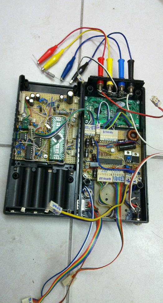
As usually, I have built just one prototype for my own education and use, and therefore only a handwritten schematics is available, due to lack of time and motivation to design a PCB. ERRATUM: Replace TL082 by the rail-to-rail type MCP6022 in the ADC buffers. In spite of using prototyping boards, I was able to squeeze the device into a case with dimensions of a typical multimeter. In a case I would eventually design a PCB, I would definitely take another version of STM32F37x in a 64 or 100 pin package and avoid the hassle with the MCP23S17 SPI port expander used here to control display and keyboard.
The device uses the 4-wire setup of course, and has four ranges of test current from 0.0005A to 0.5A. The construction is straightforward, just one has to take care to avoid the large test current to flow through the ground connections of the analog circuitry. I have used a wire from the negative current probe directly to negative battery terminal. The positive test current has a dedicated power supply for the two higher current ranges, while it goes from GPIO for the two lower current ranges. 3V3 analog, 5V analog, -5V analog have all separate power supplies from 3V3 digital and 5V digital and from the 3V3 used for large test current supply. Negative voltage probe must not be connected to analog ground, since then a part of the test current would spoil the analog ground, both voltage probes go just to the high impedance inputs of AD8253. Also do not forget robust Schottky diodes and (faster) transil at the DUT probes to prevent damage due to accidentally connecting a charged capacitor and due to the voltage spikes when switching current to an inductor.
As with all my published constructions, I use the free GNU GPLv3 license for all my source code (while the source code of the STM32F37 peripheral library employed in this project is available under the St-Microelectronics license). The complete source code with makefile and linker script in a .tar.gz archive is here. I have employed the GCC crosscompiler and flashed the code using the STM32F4 Discovery kit as a ST-LINK programmer (st-flash), see here for more details.
Calibration of the device is essential to get accurate results; list of calibration constants and instructions how to perform the calibration are in the source code.
QUICK USER MANUAL
0) Discharge a capacitor before testing. Connect the DUT in the 4-leads (Kelvin) setup. Notice that with disconnected probes, some bogus resistance might be displayed due to current flowing through the safety diodes. Resistors up to about 900 ohms can be measured at the lowest current, the limit is the voltage threshold of the safety diodes. On the other scale, tens of microohms can be measured reliably with the highest test current.
1) Press '0' repeatedly to select the component type - rotates among R,C,L,menu. Only DC resistance of an inductor is measured. In resistor mode, voltage/current is displayed at second line.
2) Press '#' and '1'-'4' to select the test current (1=0.0005A, 2=0.005A, 3=0.05A, 4=0.5A) or '#5' to enable external sync for lock-in microvoltmeter). Test current selection is INTENTIONALLY NOT INCLUDED IN AUTO-RANGING for safety - high test currents might destroy some devices. (Also, higher test currents might lead to a "self-cleaning" effect on some contacts.) During auto-ranging, the '!' sign indicates sub-optimal accuracy of the result, after successful auto-ranging it is replaced by '=' sign. Note that for certain combinations of component value and test current the auto-ranging cannot succeed.
3) Optionally press '*xy' to manually select gains of AD8253 (x=0-3) and SDADC (y=0-4)
4) To go back to auto-ranging, press '**'
5) For capacitor, optionally press '*#' to enter capacitance measurement mode, press '**' to go back to ESR mode Notice that for accurate measurement of capacitance you should select the lowest current, definitely '#1' for capacitors below 10mF. On the other hand, for ESR measurement the test current should be proportional to the capacitance of the capacitor using the lowest current for capacitances below 100uF. Optionally press '##nnn' to enter charging target voltage in mV (<400mV) for capacitance measurement.
6) Display readout should be self-explanatory, consult source code for details. Right upper corner shows measurement type, test current, auto-ranging mode, and selected voltage gains. In resistance mode, the second line shows voltage and current in mV/mA. To suppress noise and improve accuracy, long time averaging is performed, so the display update can take a few seconds.
7) USART (3V3 level) can be used to issue commands and log the results. It is NOT galvanically separated from probe leads.
8) Voltage probes are usable as a separate microvoltmeter with resolution of 0.1uV at the highest gain. Of course, this accuracy can be achieved only in the lock-in setup to cancel noise and offset. The current must thus be switched to external sync (PA5) by '#5' and current probes should be shorted to avoid a bias! The DUT must use the sync signal to provide the measured voltage only during logical high of the sync signal. Display of R is then meaningless while the first number at the second line is the voltage in mV.
9)Pressing '9' in menu mode toggles display backlight (is not recommended to achieve highest accuracy).
And some pictures of the resulting device in operation
Here you can see the ugly internals of the device ;-).
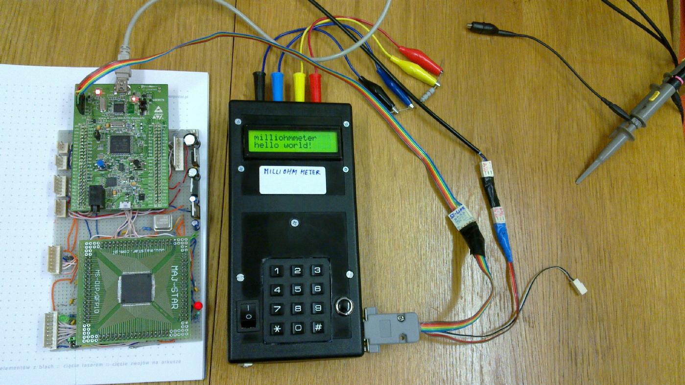
Developing the software from scratch ...
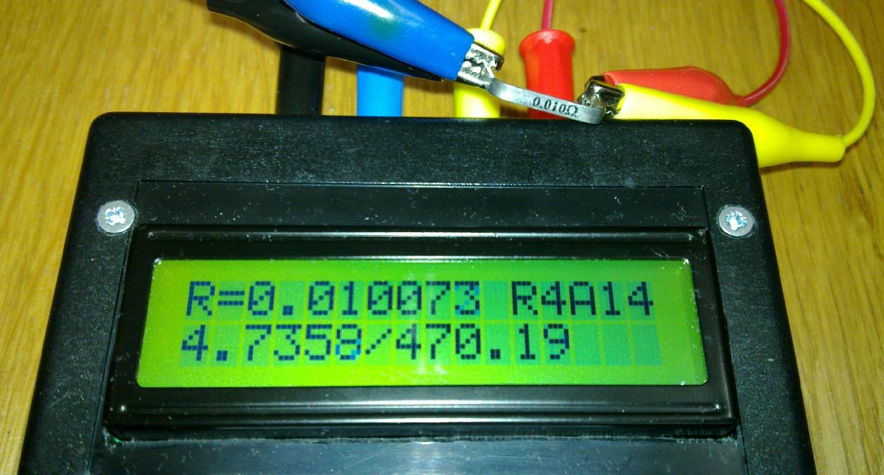
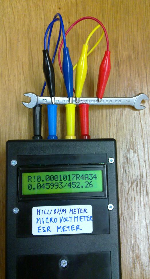
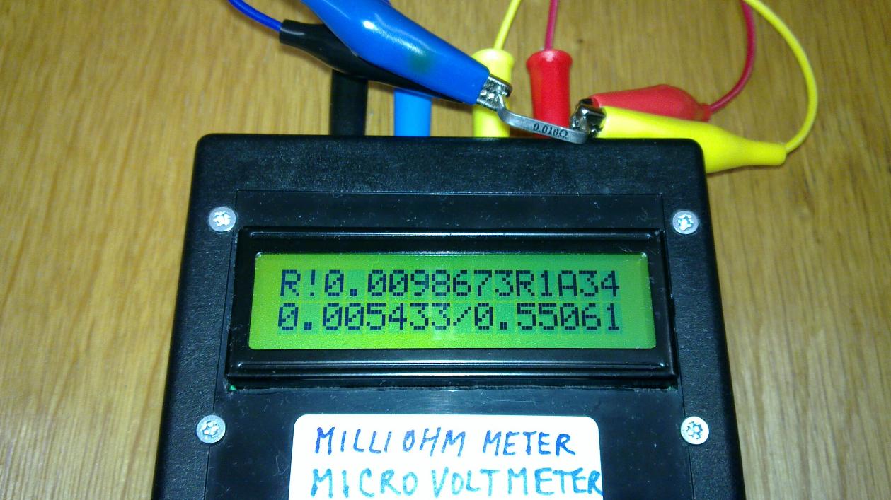
Finished instrument used to measure resistance
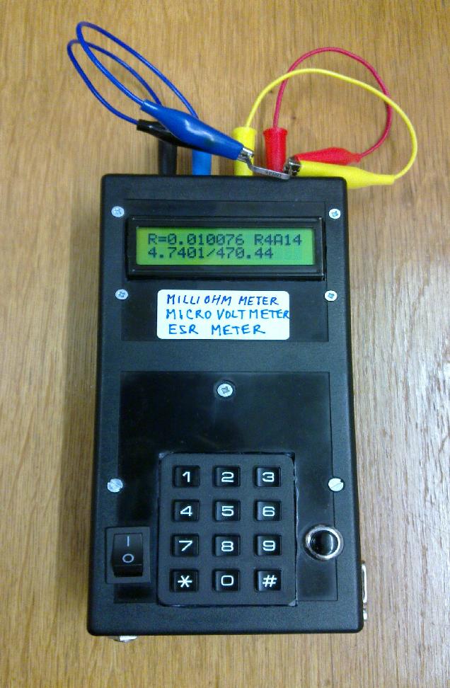
Readout matches the 10mohm resistor value quite well (it was NOT calibrated based on this resistor)
We can measure also in the microohm range. We are in the bottom 40% of the SDADC input range as indicated by the !, but still the two leading digits of the readout are stable.
and use the device also as a microvoltmeter (here demonstrated by using intentionally the 0.5mA test current and 10mohm resistor)
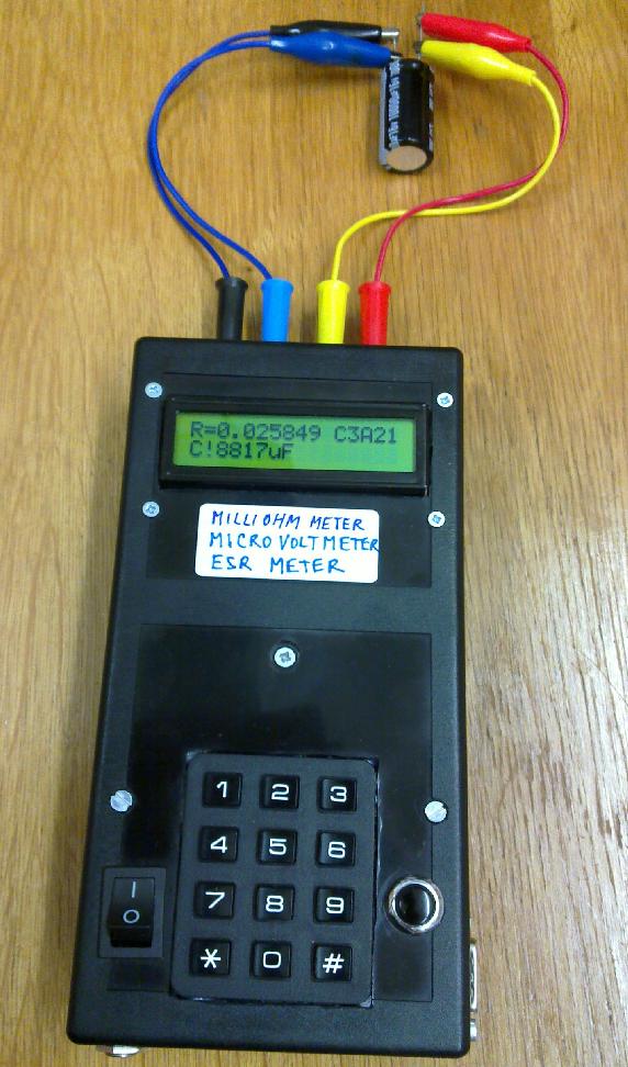
ESR of a capacitor can be measured down to a few milliohms (this device is particularly good for large capacitors, while for the small ones below 10uF it is better to use the bridge setup, since they get charged too quickly)
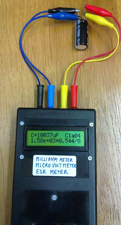
Large capacitances can be measured as well
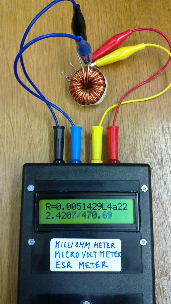
And the DC resistance of inductors can be measured as well
From my other constructions, you might be interested in a logging wattmeter with Bluetooth, based on ATmega64, again with free source code, or in a micro spot welder, suitable for example for making accu battery packs.
My Electronics page
My hobby page
My main page with e-mail contact
TOP of my family pages