Starting with the STM32F4 (discovery kit) and STM32F37x processors, flashing STM32 from linux command line
HOWTO direct stdio to DMA-based USART, using dynamic memory allocation, I2C, etc. on the STM32F4 discovery
If you need more speed than 8-bit MCUs like Atmel AVR can deliver, yet a device running Linux operating system like Raspberry Pi would be an overkill, the STM32F4 and STM32F37 series 32-bit MCUs might be an option. ST Microelectronics conveniently provides the STM32F4 discovery kit at a heavily subsidized price (cheaper than the processor itself at Farnell!), which is of the same order of magnitude as price of high-end 8-bit MCUs! Pins of the MCU are expanded to the 2.54mm pin headers, and they are 5V-tolerant (except in analog mode), really ideal for hobbyists...
I give below some code I wrote and a few tips and tricks which might be useful when developing for STM32F4 (and STM32F3), using a Linux desktop as a fully open-source development platform for cross-compilation, flashing and debugging of the embedded application. I also do not like integrated development environments, but work from the command line, using vim, make, gcc, gdb, st-flash and st-util tools, where I can have all details under direct control.
This is possible, since the Cortex-M4 core is supported by GCC 4.6 and a complete toolchain for development for this MCU is available under Linux. Excellent introduction how to install and use can be found here and here and here and on many other places, so I will not write yet another one, but address some issues I had when troubleshooting the development environment and post here some little contributions of my own.
I post here several experiments with connecting various peripherals to the STM32F4 discovery kit:
I2C contactless thermometer obtained by connecting the MLX90614 I2C temperature sensor and a text LCD display to the Discovery kit (pin connections are described in the source code, pull-ups 3k3 are used for SDA and SCL).
I have also written a set of routines to direct the libc scanf() and printf() to USART2, using DMA for the USART output and interrupts for the USART input. All the routines, including modified
I2C communication with the port expander 23017 and SPI communication with 23S17 is also included.
SPI barometer chip MPL115A was also connected, as well as MAX3100 USART chip.
Some ADC/DAC example code and some tests with counters and PWM are also incuded.
SPI Ethernet using ENC28J60 has been implemented too (details below).
Makefile and linker script (to support dynamic memory allocation) are also in the archive.
Download here the GPL-licensed source code of the above STM32F4 examples and of the SPI-Enternet implementation (cf. below): stm32f4_discovery.tar.gz
Troubles which I had to solve when starting with the STM32F4 discovery kit:
1. GCC obtained by running "summon-arm-toolchain" (Linaro GCC 4.6-2011.10) 4.6.2 reports a mysterious warning "Conflicting CPU architectures 0/13". I have rather downloaded the GCC toolchain from launchpad.net.
2. Still, sometimes -O2 or even -O1 does not work when hardware floating point is employed, program hangs in some infinite loop exception handler. With -O0 it works; seems the GCC backend for Cortex-M4 is still somewhat beta...
3. Timing of USART derived from RCC_Clocks->SYSCLK_Frequency went completely wrong. I had to edit the STM library file stm32f4xx_rcc.c and set RCC_Clocks->SYSCLK_Frequency = 168000000; instead of RCC_Clocks->SYSCLK_Frequency = pllvco/pllp;
NOTE: Actually, I found later that this was caused by a value of HSE_VALUE defined in /stm32f4xx_conf.h, which was incompatible to the Discovery kit. It is patched already in the tar file above.
4. Depending on which libc functions are called, unresolved references will appear. Some of them are probably totally bogus (_isatty, _kill) and make no sense for program running on bare silicon, some of them can be employed to direct file IO to e.g. USART (_read _write) - they are collected in stubs.c and usart.c, respectively, in the aforementioned tar file.
5. To get the dynamic memory allocation working (prerequisite for the stdio routines) required to implement _sbrk() in stubs.c and make appropriate changes in the linker script stm32_flash.ld - included in the tar.gz file.
6. When using the FPU, one has to enable it by SCB->CPACR |= ((3UL << 10*2)|(3UL << 11*2)); at the beginning of main()
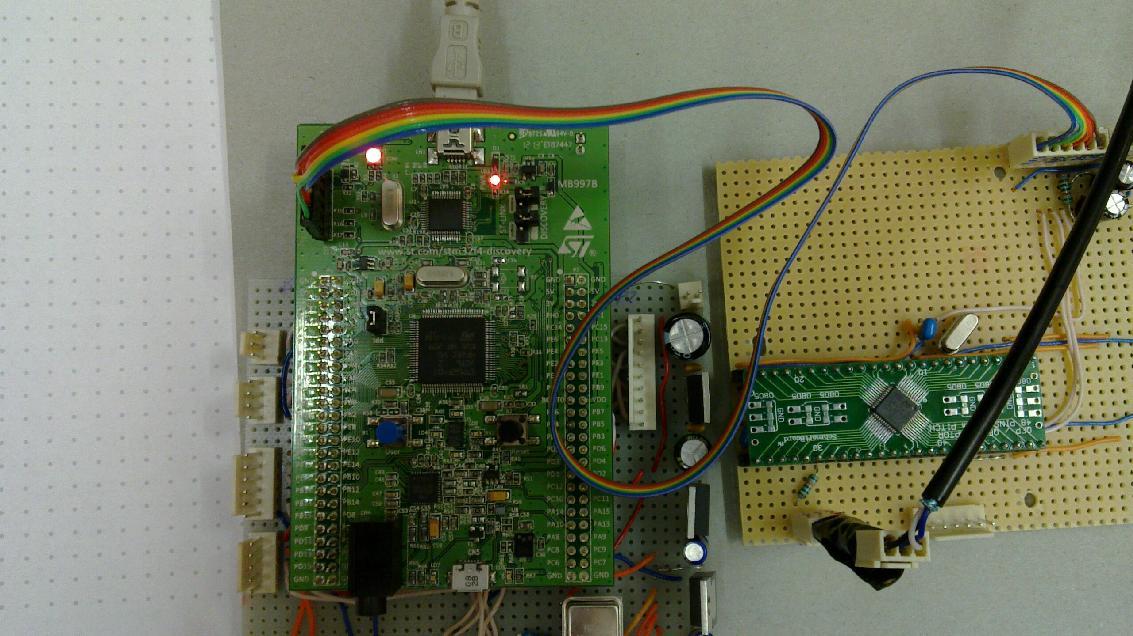
Ethernet for STM32F4 discovery kit using ENC28J60 module
STM32F4 architecture has a built-in MAC, however, there is no PHY on the discovery board. For a serious work involving design of your own board, the natural solution is to add a PHY chip, magnetics and socket to implement 100baseT ethernet. However, unless you really need the 100MBit LAN speed it is possible to use a SPI MAC+PHY chip ENC28J60, which is conveniently available together with all other needed components as a cheap module on ebay. Its connection to STM32F4 discovery kit is a matter of a few wires and it is thus very convenient for hobby projects. The 10Mbit speed is sufficient for many purposes, like WWW remote management of a device, telemetry, etc. Anyway, for applications which need 100Mbit connectivity, one can certainly ask, whether it is not better to use full TCP/IP implementation in Linux, for example employing Raspberry Pi. And finally, STM32F37 chips do not have integrated LAN support anyway and sometimes they are preferable to STM32F4 due to their accurate SDADCs, so for construction of some LAN-connected measurement devices this approach is usefull too.Concerning software, I preferred a very lightweight solution rather than using TCP/IP stack of some RTOS. I have thus ported the Arduino EtherShield stack by Guido Socher to STM32F4. This provides basic support for ICMP, TCP, UDP, HTTP etc. Non-trivial changes involved only the enc28j60.c file, while the higher-level routines maintain compatibility with arduino, which facilitates possible porting of Arduino projects based on this library. A simple test program spi_ethernet.c uses the library to send repeatedly UDP packets. At the moment, I wrote just this code to test that it works. The modified EtherShield can be found in the tar.gz file linked above.
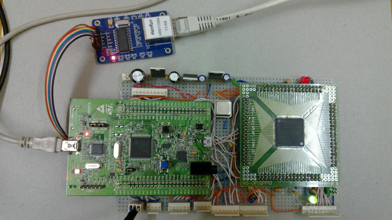
The setup is shown here (FPGA on the right is irrelevant for this project)
Using STM32F4 discovery kit as a programmer to flash STM32F372 and STM32F373 MCUs (or other STM32F3xx ones)
The STM32F4 discovery kit can serve as an inexpensive programmer for other STM32 MCUs. It does not support JTAG, but the simplified 2-wire STLINK. However, the ST-LINK utilities support both flash programming and on-chip debbuger via this connection, so for most purposes (all except the JTAG boundary scan) it is a sufficient alternative.I have recently purchased the STM32F373CCT6 chip for some prototyping including the use of the 16-bit SDADC, which is available in the LQFP48 package that can be conveniently connected to a DIP-like socket using a Schmartboard adapter. Then it suffices to connect external crystal (if HSE+PLL clock is to be used), power pins and bypass capacitors, and the pins for programming: Reset, SWDAT(PA13) SWCLK(PA14), GND and VDD (3V3), which should be connected to the SWD connector of the STM32F4 discovery board (while the STLINK jumpers on the discovery board are disconnected).
The same cross-compilation tools work for STM32F37 as did for STM32F4, since it has the ARM Cortex M4 core as well. Peripheral library, header files, linker script etc. can be downloaded from STM as well. However, when I first tried to flash a hello world program usign the STLINK utility, the st-flash command failed with the error "Unknown chip id" 0x20006432. The version of stlink in the GIT repository obviously did not support (November 2012) the relatively recent STM32F37 chip. Nevertheless, it was easy to add the device in the stlink source code, which uses the last 3 hex digits (432) as chip id, and I just copied the entry of the similar STM32F30 one, since they have the same memory layout. Here are the modified files stlink-common.c and stlink-common.h and a copy of the original STLINK license as required by the authors. After this modification, st-flash worked perfectly with the STM32F373CCT6 chip.
Serial flashing of STM32F4 or STM32F37
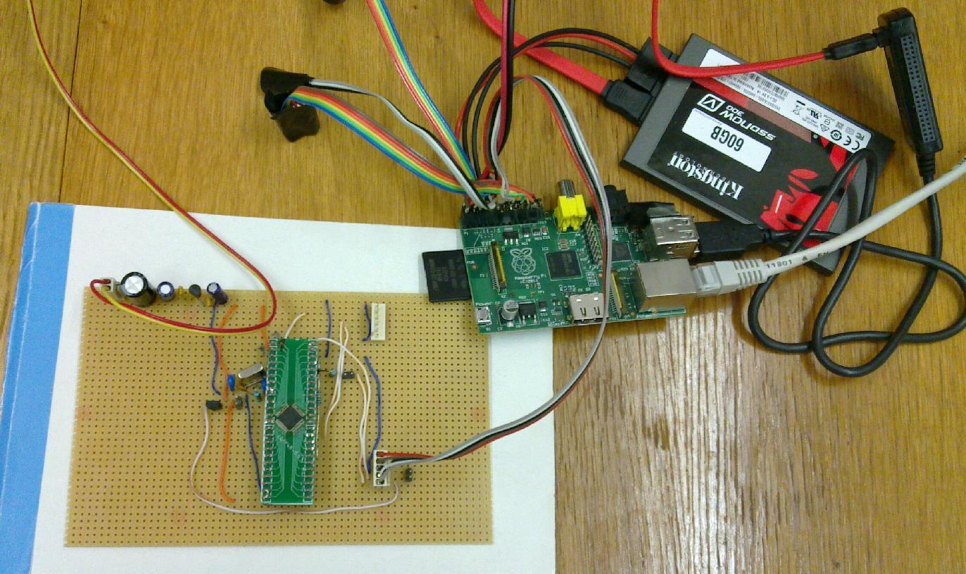
There is even simpler way how to flash STM32Fx chips, using the system bootloader. The BOOT pin and option bit have to be set appropriately to boot from system memory (BOOT1=0, BOOT0=1) and the open source program stm32flash can then be used to flash a hex file via USART. This is simplest and least expensive option, however, no on-chip debugging is supported, only flashing the code. Nevertheless it is an appealing solution in a situation when STM32 chip is integrated in one device with an embedded linux computer, like e.g. Raspberry Pi. It gives a simple possibility to upgrade the STM firmware remotely by running stm32flash on the embedded linux, using USART and two GPIO pins for reset and boot0.
However, when carefully reading the STM application notes on using the bootloader (AN2606, AN3155), it becomes apparent that a problem might be with the selection of the communication peripheral - the bootloader tests several ones and the circuit has to assure that some pins have defined values at reset etc., which complicates the schematics. For the STM32F373CCT6 device I was able to load it through USART1 without fixing any pins, but it might be not reproducible or not working with larger packages where more peripherals are pinned out. Makefile for this serial upload is available in the tar archive stm32f37.tar.gz, look for upload and rpiupload targets.
In application programming STM32F37 and STM32F4 from the linux command line
From the above reasons, the most comfortable remote firmware upgrade in devices composed of a linux system and STM32F3,4 part is in application programming with a custom bootloader. STM gives application notes AN3965 and AN4045 accompanied with sample code on this topic, however, they assume the user performs the firmware upload interactively from a Windows PC running some terminal emulator. I have thus written my own bootloader code, reusing flash interface and ymodem code from STM, to facilitate non-interactive in-application firmware upgrade from a linux command line, suitable for remote operation (e.g. via a ssh session).The application code has to be compiled and linked with a start address shifted by 0x4000 to adjust for the space occupied by the bootloader. The NVIC vectors have to be shifted as well - I have adapted the library code to do this automatically using some #ifdefs, in order that the application source code does not need any changes when moving from "normal" flashing to IAP flashing. I have tested this both on a PC with FT2232H ttyUSB adapter and on Raspberry Pi using ttyAMA0 and two GPIOs. On the linux side, program 'sb' from the package net-dialup/lrzsz is employed for non-interactive ymodem communication with the bootloader.
All the files for the IAP process can be found in the tar archive stm32f37.tar.gz. Look for iapupload and rpiiap targets in the Makefile. Notice that the page structure of flash memory differs between STM32F3 and STM32F4 series, so you have to take flash_if.c from AN3965 sample code to do it for STM32F4.
As an application of STM32F37 processor I have developed an open source milliohmmeter/ESR meter, which employes AD8253 instrumentation amplifier together with the high resolution SDADCs of STM32F373CCT6 to achieve a good accuracy in spite of simplicity of the hobby construction.
A useful site with a lot of STM32F4 information: stm32f4-discovery.com.
My Electronics page
My hobby page
My main page with e-mail contact
TOP of my family pages