A simple ESR meter in bridge configuration with ATmega8 and open source firmware
A DIY hobby construction, schematics and source codes are provided (no PCB design yet)
Since a failed aluminum electrolytic capacitor is the number one source of failures of the ubiquitous switch mode power supplies, it is handy for a (hobby) repairman to have an ESR meter to be able to quickly (in-circuit) check the equivalent series resistance (ESR) of electrolytic capacitors.There are at least two possibilities how to measure ESR of capacitors, one of them a balanced bridge configuration, where the DUT capacitor's resistance will bring the bridge out of balance, while high enough measurement frequency is used to keep the reactive component negligible. The other method uses fixed current pulses short enough to charge the capacitor only negligibly and measures the voltage on the capacitor's ESR according to the Ohm's law. I have also built an ESR/milliohmmeter based on the latter approach, using STM32F373 MCU and AD8253 amplifier. There is also an Arduino project in this direction, but I have chosen the 32-bit MCU with more accurate ADCs for this purpose. (I also became gradually a bit bored with the 8-bit MCUs, while the 32-bit ones have actually become VERY competitive in pricing, their CPU power and number of peripherals is an order of magnitude better, and development for these architectures under Linux is as easy as for the 8-bit ones.)
In the construction described below I have adopted the bridge configuration for the ESR measurement and employed the Atmel AVR ATmega8 microcontroller. As usually, I have built just one prototype for my own education and use, and therefore only a handwritten schematics is available here, due to lack of time and motivation to design a PCB. Only the analog part is drawn, the obvious pin connections of the MCU to crystal and display are just listed in the source code. The bridge configuration has been adopted, to which PB1-driven pulses are sent at a given frequency. TL084 operational amplifier is used to process the difference signal from the bridge, first DC amplification, then AC coupling, rectification, second gain stage and ADC. The resistors forming the bridge should be hand-picked to balance the bridge as well as possible, which simplifies the calibration considerably. Possibly a trimmer could be added to achieve perfect balance. Do not forget robust diodes and (faster) transil at the DUT probes to prevent damage due to accidentally connecting a charged capacitor.
As with all my published constructions, I use the free GNU GPL license for the source code esr.c. An additional headers backward.h and old_sfrdefs.h might be needed in some build environments.
Notice that the fuse bits of the ATmega must be set to switch the brownout detector reset off, otherwise the automatic powering off of the meter will not work.
Since the first amplification stage gain and the rectifier are frequency-dependent, it is necessary to calibrate the device for each measurement frequency separately. I have used four, as inductance-free as possible (definitely not wirewound), resistors: 0R22, 1R, 4R7, and 15R, measured with an accurate (milli)ohmmeter, as calibration standards. For a perfectly balanced bridge, the resulting ESR is linearly dependent on the reciprocal of the ADC readout value - for derivation see here. (Voltage reference actually compensates, so I connected Vdd of the MCU to Vref.) If the bridge were not balanced, a non-linear fit with 4 parameters would be needed. For calibration, the program outputs the ADC readouts to RS232 at 115200 baud. After the fit (x=1/ADC readout, y=reference resistance) is performed, Acoef in the code should be set to -16000*(the constant coefficient) and Bcoef to 16000/2048*(the linear coefficient). (Averaging over 2048 samples is performed to suppress the noise, calculation is done in milliohms to avoid floating point and scaled by 16 to account for roundoff errors.) After this is done, the meter will most probably still show some little non-zero resistance with shorted probes, at least at some frequencies. This offset goes to the Ccoef (directly in milliohms).
Update: Notice that the "ideal rectifier" part of the schematics could be somewhat improved, see WIKI and EEVBLOG for details.
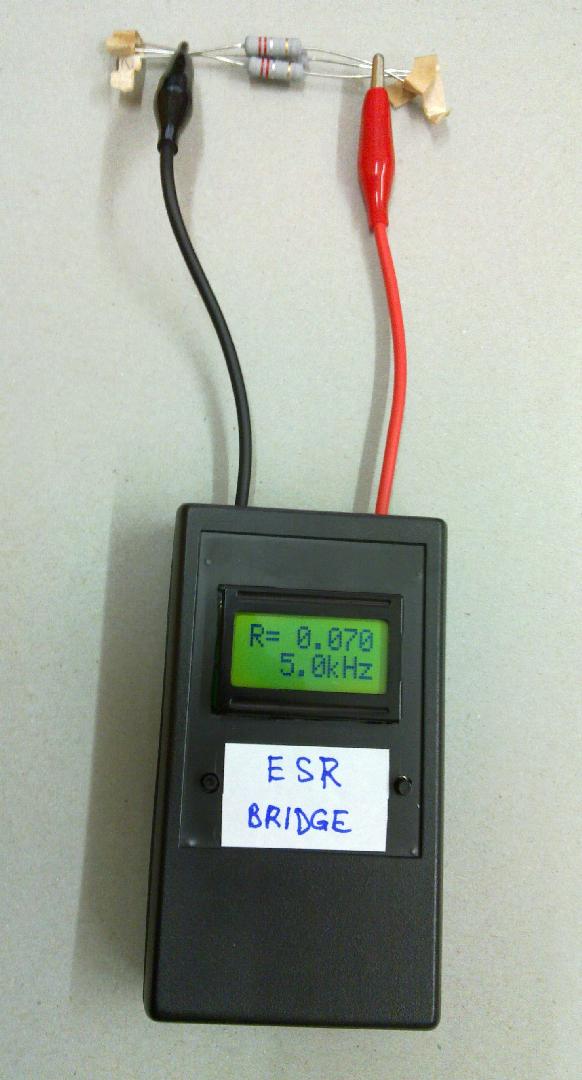
The device is powered by a 9V (re-chargeable) battery. It has two pushbuttons, the left one for switching it on (switches off automatically after a while) and the right one to change measurement frequency. The resistance is shown with 3 decimals precision, and 3 resistors 0R22 in parallel did indeed display 0.07, at least at some frequencies :-), so with a lack of better equipment the device could be misused also as a crude replacement of a milliohmmeter. However, the very low ESR of huge capacitors is definitely not measured that accurately, probably due to the neglected capacitive reactance, or effects of series inductance at higher frequencies (remember that 1 microhenry gives j63 milliohms at 10khz and we are using square pulses with a lot of harmonics!). When in doubt, you can always check readout of two identical caps in parallel and in serial to see whether the readout is reliable. Most accurate results were obtrained on the frequencies 2kHz to 100kHz, chosen according to the capacitance value.

From my other constructions, you might be interested in a logging wattmeter with bluetooth, based on ATmega64, again with free source code, or in a micro spot welder, suitable for example for making accu battery packs.
My Electronics page
My hobby page
My main page with e-mail contact
TOP of my family pages